We've just updated MediaWiki and its underlying software. If anything doesn't look or work quite right, please mention it to us. --RanAS
RGB Encoder: Difference between revisions
From SnesLab
(rename to RGB Encoder) |
(hid archive link) |
||
| Line 5: | Line 5: | ||
=== References === | === References === | ||
* [1] Figure 2-22-1, "Super NES Functional Block Diagram" on | * [1] Figure 2-22-1, "Super NES Functional Block Diagram" on [https://archive.org/details/SNESDevManual/book1/page/n98 page 2-22-2 of Book I] of the official Super Nintendo development manual | ||
* http://problemkaputt.de/fullsnes.htm#snespinoutsmiscchips | * http://problemkaputt.de/fullsnes.htm#snespinoutsmiscchips | ||
* https://wiki.console5.com/tw/images/e/e6/BA6592F.pdf | * https://wiki.console5.com/tw/images/e/e6/BA6592F.pdf | ||
Revision as of 06:08, 7 July 2023
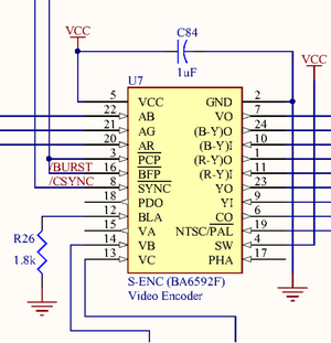
The RGB Encoder, as it is called in the official Super Nintendo development manual [1], converts analog RGB signals (pins 20, 21, and 22) from the Darlington triad to composite video output for Multi-Out. It also outputs to the RF Modulator.
References
- [1] Figure 2-22-1, "Super NES Functional Block Diagram" on page 2-22-2 of Book I of the official Super Nintendo development manual
- http://problemkaputt.de/fullsnes.htm#snespinoutsmiscchips
- https://wiki.console5.com/tw/images/e/e6/BA6592F.pdf


