We've just updated MediaWiki and its underlying software. If anything doesn't look or work quite right, please mention it to us. --RanAS
RGB Encoder: Difference between revisions
From SnesLab
(added datasheet link) |
(added video category) |
||
| Line 2: | Line 2: | ||
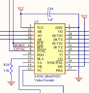
[[File:Video Encoder schematic.png|thumb|Video Encoder, in straddling regions B4 and B5 of the jwdonal schematic]] | [[File:Video Encoder schematic.png|thumb|Video Encoder, in straddling regions B4 and B5 of the jwdonal schematic]] | ||
=== References === | === References === | ||
| Line 11: | Line 7: | ||
* http://problemkaputt.de/fullsnes.htm#snespinoutsmiscchips | * http://problemkaputt.de/fullsnes.htm#snespinoutsmiscchips | ||
* https://wiki.console5.com/tw/images/e/e6/BA6592F.pdf | * https://wiki.console5.com/tw/images/e/e6/BA6592F.pdf | ||
[[Category:SNES Hardware]] | |||
[[Category:Integrated Circuits]] | |||
[[Category:ICs with unconnected pins]] | |||
[[Category:Video]] | |||
Revision as of 04:15, 5 May 2023
The Video Encoder converts analog RGB signals (pins 20, 21, and 22) from the Darlington triad to composite video output for Multi-Out. It also outputs to the RF Modulator.


