We've just updated MediaWiki and its underlying software. If anything doesn't look or work quite right, please mention it to us. --RanAS
RGB Encoder: Difference between revisions
From SnesLab
(moved image up) |
(→References: bullet points -> number) |
||
| Line 4: | Line 4: | ||
=== References === | === References === | ||
# Figure 2-22-1, "Super NES Functional Block Diagram" on [https://archive.org/details/SNESDevManual/book1/page/n98 page 2-22-2 of Book I] of the official Super Nintendo development manual | |||
# http://problemkaputt.de/fullsnes.htm#snespinoutsmiscchips | |||
# https://wiki.console5.com/tw/images/e/e6/BA6592F.pdf | |||
[[Category:SNES Hardware]] | [[Category:SNES Hardware]] | ||
Revision as of 07:20, 13 July 2023

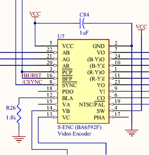
The RGB Encoder (aka Video Encoder), straddling regions B4 and B5 of the jwdonal schematic
The RGB Encoder, as it is called in the official Super Nintendo development manual [1], converts analog RGB signals (pins 20, 21, and 22) from the Darlington triad to composite video output for Multi-Out. It also outputs to the RF Modulator.
References
- Figure 2-22-1, "Super NES Functional Block Diagram" on page 2-22-2 of Book I of the official Super Nintendo development manual
- http://problemkaputt.de/fullsnes.htm#snespinoutsmiscchips
- https://wiki.console5.com/tw/images/e/e6/BA6592F.pdf

