We've just updated MediaWiki and its underlying software. If anything doesn't look or work quite right, please mention it to us. --RanAS
Darlington triad: Difference between revisions
From SnesLab
(curiously in new paragraph) |
(these darlington pairs existed way before the jwdonal schematic) |
||
| (2 intermediate revisions by the same user not shown) | |||
| Line 1: | Line 1: | ||
The '''Darlington triad''' is an array of three PNP [https://www.electronicshub.org/darlington-transistor/ Darlington pairs] | [[File:green darlington pair.png|thumb|The Darlington pair itself and some surrounding components for the green color channel, in region B4 of the [[jwdonal schematic]]]] | ||
The '''Darlington triad''' is an array of three PNP [https://www.electronicshub.org/darlington-transistor/ Darlington pairs] on the [[SNES Motherboard]], one for each of the three color channels. The pairs are: | |||
* Q3 and Q4 for red | * Q3 and Q4 for red | ||
* Q5 and Q6 for green | * Q5 and Q6 for green | ||
* Q7 and Q8 for blue | * Q7 and Q8 for blue | ||
The Darlington bases are connected directly to [[S-PPU2]] (pins 95, 96, and 97) and the Darlington emitters' signals are sent to the [[Video Encoder]] (pins 20, 21, and 22). The emitters are also connected to [[Multi-Out]] (pins 1, 2, and 4) through an alternate path that does not go through the video encoder first. On the schematic, these alternate paths are denoted as R', B', and G'. The collectors are grounded. | The Darlington bases are connected directly to [[S-PPU2]] (pins 95, 96, and 97) and the Darlington emitters' signals are sent to the [[Video Encoder]] (pins 20, 21, and 22). The emitters are also connected to [[Multi-Out]] (pins 1, 2, and 4) through an alternate path that does not go through the video encoder first. On the schematic, these alternate paths are denoted as R', B', and G'. The collectors are grounded. | ||
| Line 13: | Line 13: | ||
[[Category:SNES Hardware]] | [[Category:SNES Hardware]] | ||
[[Category:Transistors]] | [[Category:Transistors]] | ||
[[Category:Video]] | |||
Latest revision as of 18:30, 8 July 2023

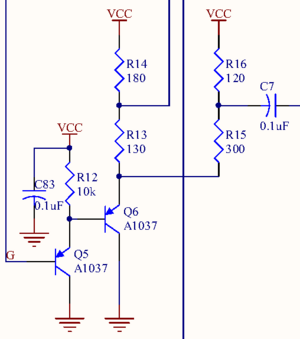
The Darlington pair itself and some surrounding components for the green color channel, in region B4 of the jwdonal schematic
The Darlington triad is an array of three PNP Darlington pairs on the SNES Motherboard, one for each of the three color channels. The pairs are:
- Q3 and Q4 for red
- Q5 and Q6 for green
- Q7 and Q8 for blue
The Darlington bases are connected directly to S-PPU2 (pins 95, 96, and 97) and the Darlington emitters' signals are sent to the Video Encoder (pins 20, 21, and 22). The emitters are also connected to Multi-Out (pins 1, 2, and 4) through an alternate path that does not go through the video encoder first. On the schematic, these alternate paths are denoted as R', B', and G'. The collectors are grounded.
Curiously, the green channel is unique in that Q5 and R12 are in parallel with the polarized C83, but there is no corresponding capacitor for the blue and red Darlington pairs.
