Sprite Creation with Dyzen
| English | Português | Español | 日本語 |
The following tutorial will explain how to create sprites using Dyzen. This tutorial covers not just how to use the tool, but also general functions for the creation of regular, cluster, and extended sprites.
For this tutorial, it's assumed that the developer has previous knowledge of ASM like using basic commands, branching, and indexing. This tutorial is based more on how to construct the logic of a sprite.
Also, it should be noted that this tutorial can also serve for sprites which are not created with Dyzen, though the focus is ultimately based on those.
Creating a CFG/JSON with CFG Editor
Sprite Structure
A sprite is structured in the following manner:
-
Sprite Init: This is the routine which occurs when the sprite is spawned. In Pixi, this routine begins with the line:
print "INIT ",pc
And should end with an RTL.
-
Sprite Main: This routine is called in each Game Loop (SNES Frame) and is used for updating the sprite and its logic. In PIXI, this routine begins with the line:
print "MAIN ",pc
And should end with an RTL. Usually this routine would be like so:
print "MAIN ",pc
	PHB
	PHK
	PLB
	JSR SpriteCode
	PLB
RTL
This calls a routine named SpriteCode which will have the real contents of this routine. This is performed to better organize the code. Also, the Program Bank is set so that the tables can be indexed with short absolute indexing ($XXXX,x o $XXXX,y), instead of using long indexing, optimizing the number of cycles the code uses.
-
SpriteCode: It basically contains the Main routine, as described above. This routine is called by others which will carry out the logic of the sprite. We will separate these routines into DynamicRoutine, GraphicRoutine, InteractionWithPlayer, InteractionWithSprites, StateMachine, AnimationRoutine, etc., depending on whatever the sprite requires. The basic structure of this routine is:
SpriteCode:

.AlwaysExecutedZone
	JSR GraphicRoutine                  ;Calls the graphic routine and updates sprite graphics

	;Here you can put code that will be excecuted each frame even if the sprite is locked

	LDA !SpriteStatus,x
	CMP #$08                            ;if sprite dead return
	BNE Return

	LDA !LockAnimationFlag
	BNE Return			                    ;if locked animation return.

.ExecutedIfNotLocked
	%SubOffScreen()

	JSR InteractMarioSprite
	;After this routine, if the sprite interact with mario, Carry is Set.

	;Here you can write your sprite code routine
	;This will be excecuted once per frame excepts when
	;the animation is locked or when sprite status is not #$08

	JSR AnimationRoutine                ;Calls animation routine and decides the next frame to draw
RTS
Return:
RTS
Here we can take note of 2 main zones (blocks of code):
- .AlwaysExecutedZone which encompasses the area from the beginning of the routine until the first check
LDA !SpriteStatus,x. This zone always runs, even if the game is paused or the animations are stopped, normally we don't put a lot of code in this zone, except for graphics routines. - .ExecutedIfNotLocked encompasses the area after the check
LDA !LockAnimationFlag. This zone runs when the animations aren't stopped, the game isn't paused, or the player is not in the death animation, etc. Also, it should be clarified that this sector is only executed if the !SpriteStatus,x has the value 8. This means that the sprite has the status "Normal Routine". This RAM address corresponds with the table$14C8. It should be noted that the check of!SpriteStatus,xcan be modified so that the sprite executes the code in other statuses. One common state is 2, which means the sprite is dying. In this area, we can note that it calls other routines that we're going to detail further along in the tutorial. For now, it's important to know that below, we callJSR InteractMarioSprite. This is where we will execute the code for the sprite's logic.
- .AlwaysExecutedZone which encompasses the area from the beginning of the routine until the first check
State Machines
A state machine is made up of 2 main parts, the states and the transitions between states. In these machines, only one state executes at a time, and it changes according to logical conditions implemented within each state.
This isn't a complete course on state machines, because this material can take semesters of study for deepening all the distinct dimensions. Nevertheless, we will use this concept for putting together the logic of our sprite.
With this scheme, the idea is to take the central routine called StateMachine, which will be used for calling the correct routine according to the state that's executing. To do this, we will need a table of sprites which we'll use for this purpose. It's highly recommended to use a misc table, so we don't need to find freeram that can end up being used by other resources. For this we have to look at the top of the code, in the marked zone with the comments:
;######################################
;############## Defines ###############
;######################################
We can add the variable:
!State = !SpriteMiscTable8
Using one of the misc sprite tables that can be used for whatever purpose we want.
Once this is done, we will need to give this variable a value of 0. We will use the state 0 for our initial state. Now we mustn't always initialize it as 0. For example, we could use the extra byte or extra property to set the initial state of the sprite, to create different versions of the same sprite, but normally we use the state 0 as the initial state. To do this, we will add the line on SpriteInit:
STZ !State,x ;!State,x = 0
Soon we'll create a routine named "StateMachine" that executes a different routine, depending on the variable !State,x. This routine will be the following:
StateMachine:
	LDA !State,x	;A Reg = !State,x
	ASL
	TAX		;Transform A Reg into a index value for table States and put that value in the X Reg

	JSR (States,x)	;Call Routine on the table States using X reg value.
RTS

States:
	dw State0
	dw State1
	dw State2
	.
	.
	.
We can note that this routine uses a table named "States". In this table, we will put all the states that our sprite can have as it's running, being stopped, turning, dying, etc. It isn't necessary to put the name of the states "State0". Simply use the name that you think is most conventient. Now normally, it's recommended to number them because it serves to remember the value of the variable !State,x that's used to call each state.
For those that know some high level programming, this routine would be the equivalent of:
switch(state)
{
	case 0:
		state0();
		break;
	case 1:
		state1();
		break;
	case 2:
		state2();
		break;
	case 3:
		state3();
		break;
	etc...
}
We will be able to place this routine in any sector under the routine "SpriteCode". Just try to be tidy, because in ASM it's very easy for the code to become a disaster. Once this routine is created, we'll call it in the zone of the routine "SpriteCode" which happens before the JSR AnimationRoutine. Nevertheless, if we try the sprite right now, it won't insert, because the labels haven't been created for each state.
State Structure
For making each of the states, we'll follow this template:
StateX:
	LDX !SpriteIndex	;Load Sprite index on X Register
	LDA !AnimationIndex,x
	CMP #$XX		;Index of the animation represented by the State
	BEQ .StateLoop
.StateStart
	JSR ChangeAnimationFromStart_XXXX	;Change the animation to the animation with index #$XX
RTS
.StateLoop
RTS
What we can note, this template has 2 sections:
- .StateStart which is called when the sprite changes from one state to another.
- .StateLoop which is called for each frame after the state has begun. Note that this template links states to one and only one animation at the same time. It can be made so each state uses more than one animation making modifications to its structure, but in the practice of making this, it usually isn't very necessary and has the disadvantage of making the code more disorderly and difficult to read. What's more, it complicates the logic of the state. So I recommend using 1 animation and only 1 for a state unless it's really necessary.
Something that we can note about this structure, is that from outside the state, we can call both the "StateStart" and "StartLoop" using the JSR StateX_StateStart and JSR StateX_StateLoop commands. Calling "StateStart" can be useful in certain circumstances, when we need to begin a state externally. This is common especially in dynamic sprites or flip animations. Now calling "StateLoop" is not so useful. We could rarely find a reason for calling this section externally unless we had another state that was almost identical but with a little variation.
Another important detail to note is that the state at the beginning has an LDX !SpriteIndex. This is because the sprites use tables for their variables and these tables use the sprite index stored in the X register to be able to access the value of the table. However, when we called the "StateMachine" routine, the value of the X register was modified, and we lost the index of the sprite in the X register. So we used this command to restore it.
Finally, there's a question, "How do I know the index of the animation used in this state?" This is answered by going to the section of the code where the ChangeAnimationFromStart routines are. There can find something like this:
ChangeAnimationFromStart_Walk:
	STZ !AnimationIndex,x
	JMP ChangeAnimationFromStart
ChangeAnimationFromStart_Flip:
	LDA #$01
	STA !AnimationIndex,x
	JMP ChangeAnimationFromStart
ChangeAnimationFromStart_Resist:
	LDA #$02
	STA !AnimationIndex,x
	JMP ChangeAnimationFromStart
ChangeAnimationFromStart_DeathLoop:
	LDA #$03
	STA !AnimationIndex,x
	JMP ChangeAnimationFromStart
ChangeAnimationFromStart_Death:
	LDA #$04
	STA !AnimationIndex,x
Where the value loaded in A would be the index of the corresponding animation. In this example:
Walk => !AnimationIndex,x = 0
Flip => !AnimationIndex,x = 1
Resist => !AnimationIndex,x = 2
DeathLoop => !AnimationIndex,x = 3
Death => !AnimationIndex,x = 4
Conditions and Transitions
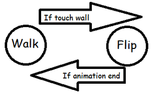
Transitions allow states to change from one to another under certain circumstances. Each state can change to a limited number of other states so that the sprite has the intended behavior. For example, if we had a sprite that simply moved from side to side without detecting ledges, we would need a machine like this:
We would have a sprite that would walk in a straight line until it ran into a wall, then it would change to the flip state, playing that animation. When the flip animation finishes, then it would return to the walk state, going to the other side. And in ASM, that machine would look like this:
StateMachine:
	LDA !State,x	;A Reg = !State,x
	ASL
	TAX		;Transform A Reg into a index value for table States and put that value in the X Reg

	JSR (States,x)	;Call Routine on the table States using X reg value.
RTS

States:
	dw Walk0
	dw Flip1

Walk0:
	LDX !SpriteIndex	;Load Sprite index on X Register
	LDA !AnimationIndex,x
	CMP #$00		;Index of the animation represented by the State
	BEQ .StateLoop
.StateStart
	JSR ChangeAnimationFromStart_Walk	;Change the animation to the animation with index #$XX

	LDA !GlobalFlip,x
	BEQ .right		;Check if is sprite direction is right or left
	LDA #$E0		;If sprite direction is left then set negative X Speed
	BRA ++
.right
	LDA #$20		;If sprite direction is right then set positive X speed
++
	STA !SpriteXSpeed,x
	JSL $01802A|!rom			;Update Sprite position with gravity
RTS
.StateLoop
	JSL $01802A|!rom	;Update Sprite position with gravity

	LDA !SpriteBlockedStatus_ASB0UDLR,x
	AND #$03
	BEQ +					;Check if Left or Right wall are blocked
	LDA #$01
	STA !State,x				;If left or right are blocked then change to state flip
+
RTS

Flip1:
	LDX !SpriteIndex	;Load Sprite index on X Register
	LDA !AnimationIndex,x
	CMP #$01		;Index of the animation represented by the State
	BEQ .StateLoop
.StateStart
	JSR ChangeAnimationFromStart_Flip	;Change the animation to the animation with index #$XX
	STZ !SpriteXSpeed,x			;X Speed = 0
	JSL $01802A|!rom			;Update Sprite position with gravity
RTS
.StateLoop
	JSL $01802A|!rom			;Update Sprite position with gravity

	LDA !AnimationFrameIndex,x
	CMP #$XX
	BCC +					;Checks the last frame of the animation

	LDA !AnimationTimer,x
	BEQ +					;Check if the frame finished

	LDA !GlobalFlip,x			;If animation finish
	EOR #$01				;
	STA !GlobalFlip,x			;Alternate sprite direction

	STZ !State,x				;State = Walk
	JSR Walk0_StateStart			;Call Walk0 State Start
+
RTS
Let's analyze the code. First, we can note that it has 2 states as shown in the diagram. The first is Walk, with index 0, and the second is Flip, with index 1. Let's start by looking at the Walk0 state. This has the following condition in "StateStart".
	LDA !GlobalFlip,x
	BEQ .right		;Check if is sprite direction is right or left
	LDA #$E0		;If sprite direction is left then set negative X Speed
	BRA ++
.right
	LDA #$20		;If sprite direction is right then set positive X speed
++
	STA !SpriteXSpeed,x
This condition first checks the variable !GlobalFlip,x. This has the value 0 if the sprite faces right, or 1 if it faces left (It can be the other way around depending on how the sprite was made in Dyzen). Then, if the sprite faces right (!GlobalFlip,x is 0), then it loads a positive value in register A. Otherwise it loads a negative value in register A. Next it executes STA !SpriteXSpeed,x, which sets the speed of the sprite. Then refresh the sprite's screen position with JSL $01802A|!rom.
Now in the "StateLoop" section, we can note the following check:
	LDA !SpriteBlockedStatus_ASB0UDLR,x
	AND #$43
	BEQ +					;Check if Left or Right wall are blocked
	LDA #$01
	STA !State,x				;If left or right are blocked then change to state flip
+
This will check the flags of the variable !SpriteBlockedStatus_ASB0UDLR,x, where:
- A: Flag which is 1 if the sprite is touching a solid block on layer 2 from above (Floor detection).
- S: Flag which is 1 if the sprite is touching a solic block on layer 2 from the side (Wall detection).
- B: Flag which is 1 if the sprite is touching a solid block on layer 2 from below (ceiling detection).
- U: Flag which is 1 if the sprite is touching a solid block on layer 1 above (ceiling detection).
- D: Flag which is 1 if the sprite is touching a solid block on layer 1 below (floor detection).
- R: Flag which is 1 if the sprite is touching a solid block on layer 1 to the right (right wall detection).
- L: Flag which is 1 if the sprite is touching a solid block on layer 1 to the left (left wall detection).
We use the AND command so that all the flags which we don't need stay at 0. In this case, we are detecting walls, so we don't need the flags A, B, U, and D. So the value #$43 is used, which in binary would be #$01000011. So if the A register, after using the AND, is different from 0, then it is touching a wall. After this, It would change the value of !State,x so that it uses the Flip state.
It should be noted in this case that the routine JSL $01802A|!rom updates the value of !SpriteBlockedState_ASB0UDLR,x. This is why it's called at the beginning of "StateLoop" and not at the end.
Now we'll review the Flip state. The first thing to note is that it also updates the position of the sprite. An unsuspecting person might think that they don't need to update the position during the Flip routine, since the sprite shouldn't move when it's touching a wall. However, this is not true, and that's in case a sprite isn't touching the ground. Therefore, the vertical position must be updated.
The "StateStart" in this case is very simple. Merely set the horizontal speed to 0. The interesting thing in this state happens during "StateLoop". Here we can notice the following checks:
	LDA !AnimationFrameIndex,x
	CMP #$XX
	BCC +					;Checks the last frame of the animation

	LDA !AnimationTimer,x
	BEQ +					;Check if the frame finished

	LDA !GlobalFlip,x			;If animation finish
	EOR #$01				;
	STA !GlobalFlip,x			;Alternate sprite direction

	STZ !State,x				;State = Walk
	JSR Walk0_StateStart			;Call Walk0 State Start
+
We start with:
	LDA !AnimationFrameIndex,x
	CMP #$XX
	BCC +
This checks the variable !AnimationFrameIndex,x. We can use this variable to know which frame within the animation is being played. Therefore, the idea would be to check if the frame that is played is the last frame of the animation. "How can we know what value to put in #$XX?" You can go to the table of that animation. In the animation routine, there is a table called "Frames". Example:
Frames:
Animation0_Walk_Frames:
	db $00,$01,$02,$03,$04,$05,$06,$07
Animation1_Flip_Frames:
	db $08,$08
Animation2_Resist_Frames:
	db $09
Animation3_DeathLoop_Frames:
	db $0A,$0B
Animation4_Death_Frames:
	db $0C,$0D,$0E,$0F,$10
In this example, we can note that the animation for Flip has only 2 frames. Then the value that we would have to put is #$01 (size of the animation - 1).
Another method for knowing what number to put is to go to the table "AnimationLenght", which has the size for each animation. Example:
AnimationLenght:
	dw $0008,$0002,$0001,$0002,$0005
We can note that this table shows the size of each of the animation. In this case:
Walk => Size 8 frames, last frame #$07
Flip => Size 2 frames, last frame #$01
Resist => Size 1 frames, last frame #$00
DeathLoop => Size 2 frames, last frame #$01
Death => Size 5 frames, last frame #$04
Once we understanding how this check works, we will go to the next one:
	LDA !AnimationTimer,x
	BEQ +
This is quite simple. It shows us that the variable !AnimationTimer,x contains the number of Game Loops (SNES Frames) before the frame will change. Therefore, if it has a value different from 0, it means that the frame is still playing.
After these 2 checks, we use these commands:
	LDA !GlobalFlip,x			;If animation finish
	EOR #$01				;
	STA !GlobalFlip,x			;Alternate sprite direction
The command EOR can be used to toggle the bits in register A. For example, EOR #$01 would toggle the rightmost bit. So if that bit was 0, it would change to a 1. If it was a 1, it would change to a 0. We use this to taggle the sprite's direction.
Finally, it goes back to the Walk state, but also the "StateStart" of the walk state is called. The reason for this is that when alternating the direction of the sprite, the sprite would show the animation flipped incorrectly for 1 frame. Therefore, in the flip states, it is very common to call "StateStart".
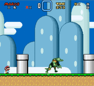
Here we can see the results of this behavior:
Movement
Basic Movement
Advanced Movement
Interaction
Dyzen has its own system of interaction. However, it's not mandatory to use it, so I will delve into the different ways of interacting between the sprite and other entites of the game such as the player, projectiles, other sprites, etc. In this section, we will also see certain actions that can be performed when a collision is detected.
Collision Detection with Player
Vanilla
To detect if the sprite interacts with the player, first we must select the Sprite Clipping that we want in the CFG editor. It will appear in the below square below:
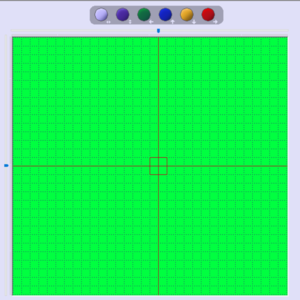
We must consider that the dark blue square that comes out would be equivalent to the square with a red border that comes out in the center in Dyzen:
Therefore, when doing the sprite in Dyzen, you should consider this, to put the graphics in the correct position to fit with the Hitbox.
If your sprite has a common interaction, maybe you don't need to do anything in the ASM, as long as you keep the "Don't use default interaction with Mario" box blank. But if you need to do something out of the ordinary, you can use the following commands:
	JSL $03B664|!rom	;Load Player Hitbox/Clipping
	JSL $03B69F|!rom	;Load Sprite Hitbox/Clipping
	JSL $03B72B|!rom	;Check For contact between Player and Sprite
	BCC +
.ThereIsContact
	;Here put the code that happends when contact between Player and Sprite exists.
+
As we can see, first the player's hitbox is loaded, then that of the sprite, and then another routine is called to check if there is contact between them.
Custom
For a custom routine, it is practically the same as the vanilla routine. What changes is that you must load the hitbox of the sprite manually. For this we can use the following RAM addresses:
- $00 (!Scratch0): Low byte of the X position of the hitbox.
- $01 (!Scratch1): Low byte of the Y position of the hitbox.
- $02 (!Scratch2): Width of the hitbox.
- $03 (!Scratch3): Height of the hitbox.
- $08 (!Scratch8): High Byte of the X position of the hitbox.
- $09 (!Scratch9): High Byte of the Y position of the hitbox.
Therefore, the proper way to use to use it would be something like the following:
	JSL $03B664|!rom	;Load Player Hitbox/Clipping

	LDA !SpriteXHigh,x	;Load Sprite X High Byte
	XBA			;
	LDA !SpriteXLow,x	;Load Sprite X Low Byte
	REP #$20		;A 16 bits = X position
	CLC
	ADC #!OffsetX		;A = Sprite X position + Hitbox X Offset (Offset must be 16 bits)
	SEP #$20
	STA !Scratch0		;Store Hitbox X Low Byte
	XBA
	STA !Scratch8		;Store Hitbox X Low Byte

	LDA !SpriteYHigh,x	;Load Sprite Y High Byte
	XBA			;
	LDA !SpriteYLow,x	;Load Sprite Y Low Byte
	REP #$20		;A 16 bits = Y position
	CLC
	ADC #!OffsetY		;A = Sprite Y position + Hitbox Y Offset (Offset must be 16 bits)
	SEP #$20
	STA !Scratch1		;Store Hitbox Y Low Byte
	XBA
	STA !Scratch9		;Store Hitbox Y Low Byte

	LDA #!Width
	STA !Scratch2		;Store Hitbox Width
	LDA #!Height
	STA !Scratch3		;Store Hitbox Height

	JSL $03B72B|!rom	;Check For contact between Player and Sprite
	BCC +
.ThereIsContact
	;Here put the code that happends when contact between Player and Sprite exists.
+
As we can see, it's the same routine, only this time we hand over the parameters manually instead of defining them in the CFG. Basically, the position of the hitbox is loaded (Hitbox Offset + Sprite Position), and the width and height are loaded.
Interaction with Dyzen
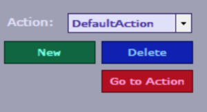
Dyzen's system is a generalization of the custom interaction, only instead of specifying the parameters like before, it makes a loop which checks the different hitboxes according to a table. With this system, each hitbox has an action which is defined in the "Interaction" section of Dyzen:
Then that action is called when there is contact between the respective hitbox and the player.


